Cable Gland Installation Procedure
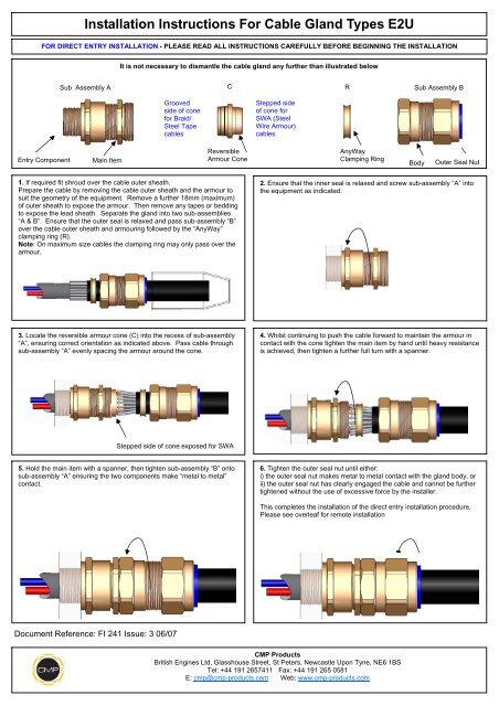
Installation Instructions For Cable Gland Types E2u Cmp Products
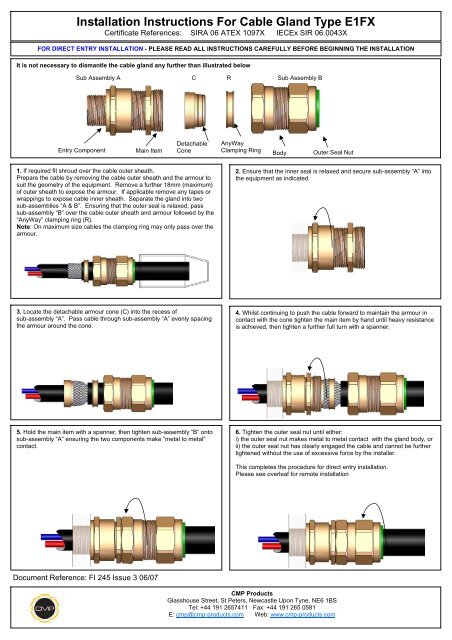
Installation Instructions For Cable Gland Type E1fx Cmp Products

Installation Instructions For Cable Gland Type Cx Cmp Products
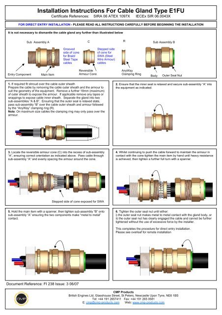
Installation Instructions For Cable Gland Type E1fu Cmp Products
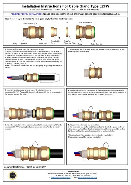
Installation Instructions For Cable Gland Type E2fw Cmp Products
What Is A Cable Gland Instrumentation Tools
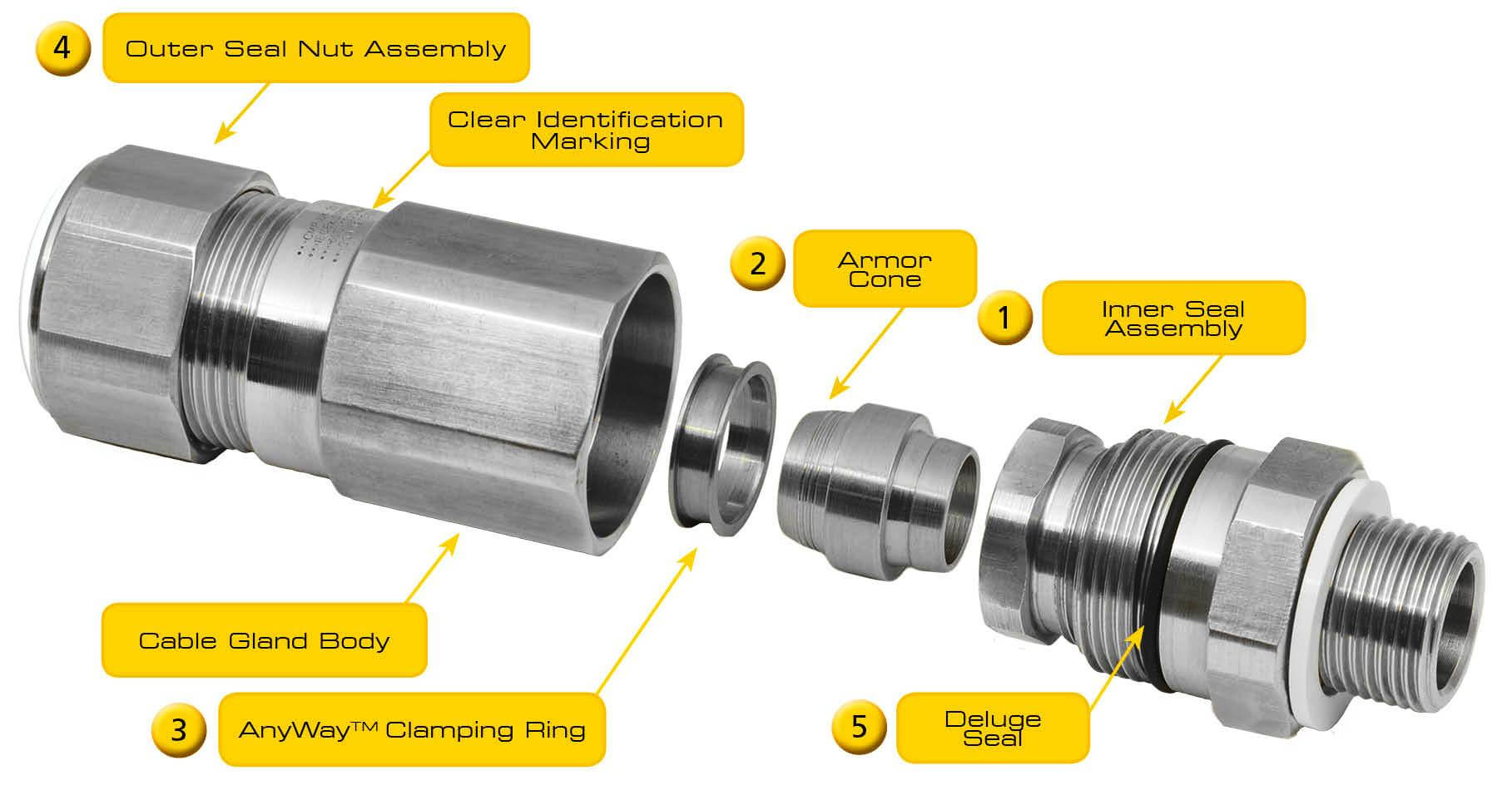
Procedure cmp cable gland installation general requirements all works shall be carried out in accordance with the approved project specifications drawings diagrams schedules lists data specification sheet and relevant approved itp s and procedure with manufacturer s recommendation as required.
Cable gland installation procedure.

Steel Wire Armour Cables Maintaining Earth Continuity
Https Www Nexans Co Nz Eservice Newzealand En Nz Documentdownload 73320 Installation Instructions

Cmp A2f Cable Glands Installation Instruction Manualzz
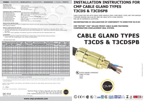
T3cds Installation Instructions Cmp Products
Source : pinterest.com
